|
|
GMPLS-controlled Ethernet Label Switching (GELS)
Provider Backbone Transport (PBT), as specified in IEEE 802.1Qay, provides capability for the establishment of a layer-2 platform for explicit provisioning and management of the network. Besides, the IEEE and ITU are actively developing a set of standards such as the Continuity Fault Management (CFM) specification of
IEEE 802.1ag, aimed at providing Ethernet with a set of service-based performance monitoring and resilience mechanisms.
To fulfill those functionalities, it is only natural to turn to the mature and widely accepted control-plane framework of Generalized MultiProtocol Label Stiwching (GMPLS). The use of GMPLS in an Ethernet context requires adapting GMPLS signalling protocols to the particularities of PBT and CFM frameworks. To address those issues, a number of Internet Engineering Task Force (IETF) drafts are being developed within its Common Control and Measurement Plane (ccamp) Workgroup.
A Word About CFM
Specified in 802.1ag, Connectivity Fault Management (CFM) defines end-to-end layer-2 Operations, Administration, and Maintenance (OAM) functions. CFM introduces a hierarchical architecture where eight management levels enable customers, service providers, and network operators to run OAM processes in their own nested maintenance domains (MDs). The edge nodes of an MD are called Maintenance End Points (MEPs) and initiate OAM mechanisms, whereas intermediate nodes (Maintenance Intermediate Points, MIPs) only respond to them.
The foremost fault management functionality specified by CFM is Connectivity Check. Within each MD, MEPs multicast periodic Connectivity Check
Messages (CCMs). CCMs may be used to detect loss of connectivity or network misconfiguration, and to measure frame loss. In each MD, each Ethernet connection is assigned a unique Maintenance Association ID (MAID) that is associated to CFM parameters such as the fixed time intervals between consecutive CCMs.
GMPLS and its Ethernet Extensions
GMPLS introduces a connection-oriented control plane. It expands MPLS from being
limited to a single data-plane type (packet switching) to supporting a wide
range of data plane types (Time Division Multiplexing, TDM; Wavelength Division
Multiplexing, WDM; Space Division Multiplexing, SDM; etc.). This is accomplished
through the use of generic labels such as wavelength (WDM), fibre (SDM), and time-slot (TDM).
GMPLS decouples control plane and data plane and relies on IP protocols such as Resource Reservation Protocol (RSVP) for signalling, Open Shortest Path First (OSPF) or Intermediate System to Intermediate System (IS-IS) for routing, all extended to allow Traffic Engineering (TE). For local operations such as neighbouring node discovery, data and control channel connectivity, and link fault management, GMPLS relies on its own Link Management Protocol (LMP). Ethernet extensions to GMPLS are introduced below for each of the described GMPLS components:
- Routing: OSFP-TE and IS-IS-TE do not require modification to run over PBT Ethernet networks.
- Link Management: In Carrier-Grade Ethernet networks, the key elements of LMP (link-level discovery, connectivity monitoring, and fault management) are taken over by CFM procedures and the Link-Layer Discovery Protocol (LLDP), hence LMP is not a requirement in GELS.
- Signalling: The major Ethernet-related modifications to GMPLS arise in RSVP-TE and are described below.
GELS Signalling Specifics
PBT defines ESPs as unidirectional paths identified by the backbone MAC destination address (B-DA) and the backbone VLAN ID (B-VID). Since forwarding depends on those two parameters, their combination can be viewed as the path label. However, a particularity of PBT is that the MAC addresses are fixed and have global significance, thus ESP labels are global and cannot be swapped. To insure the label uniqueness for each unidirectional ESP, each edge Provider Backbone Bridge (PBB) is assigned the tasks of allocating B-VIDs to ESPs terminating at its MAC address, and maintaining a list of all allocated B-VIDs.
Unlike PBT, GELS uses PBT’s unidirectional ESPs to establish bidirectional connections. RSVP-TE is extended to enable the simultaneous creation of two counter-directional one-way ESPs. A GELS connection is hence defined by its end-point backbone MAC addresses and two distinct B-VIDs, one identifying a unidirectional ESP in each direction.
A requested ESP can be merged with an existing ESP provided they have a common destination PBB (B-DA) through allocation of the same B-VID, thus creating MultiPoint-to-Point (MPtP) ESPs. The GELS extensions to RSVP-TE provide further mechanisms to verify the eligibility of ESP merging (shared forwarding) requests and to guarantee resource allocations for each established connection.
GELS Signalling Example
In Fig. 1, Tacáks et al. depict a sample RSVP-TE set-up of a GELS connection. This is a break-up of the protocol steps:
- The route of the bidirectional connection is built at the source PBB or remotely. Corresponding CFM parameters such as the MAID are determined.
- After checking its VLAN allocation table, the source PBB (MAC-A) pre-assigns an unused B-VID (VID-2) to the upstream ESP.
- The source PBB requests the establishment of a connection through a Path message that includes a number of required parameters such as the upstream label < MAC-A, VID-2 >, route information, CFM parameters, and TE requirements. (Fig. 1 (a))
- Upon receiving the Path message, intermediate nodes update their forwarding tables by including the fixed upstream port-ESP associations. (Fig. 1 (b))
- Upon receiving the Path message, the destination PBB (MAC-B) checks its VLAN allocation table and assigns an unused B-VID (VID-1) to the downstream ESP. (Fig. 1 (b))
- The destination PBB uses the received OAM information to set-up a MEP entity. (Fig. 1 (b))
- The downstream label < MAC-B, VID-1 > is transmitted to the source PBB in a Resv message, along with other pertinent OAM information. (Fig. 1 (b))
- Upon receiving the Resv message, the source PBB sets up a MEP entity for the connection. (Fig. 1 (c))
- Upon receiving the Resv message, intermediate nodes update their forwarding tables by including the fixed downstream port-ESP associations. (Fig. 1 (c))
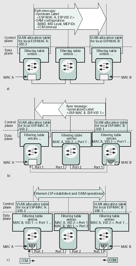
Fig. 1 Set-up of bidirectional ESP with connectivity monitoring (Tacáks et al.)
GELS Advantages
The GMPLS automated control plane provides the following advantages to Carrier-Grade Ethernet:
- Explicit control of ESP set-up, tear-down, and TE parameters.
- Improved control of configuration, monitoring, and recovery processes at various granularities.
- Improved vendor equipment interoperability.
- Reduced down time after failures due to real-time automated service and network restoration.
- Reduced configuration errors due to automated configuration tools such as auto-discovery.
- Reduced operational costs
Further Reading
- A. Tacáks; H. Green; B. Tremblay, "GMPLS Controlled Ethernet: An Emerging Packet-Oriented Transport Technology," IEEE Communications Magazine, vol.46, no.9, pp.118-124, Sep. 2008.
- Common Control and Measurement Plane (ccamp) Workgroup, The Internet Engineering Task Force (IETF),
http://www.ietf.org/html.charters/ccamp-charter.html
|
|
|
|
| |